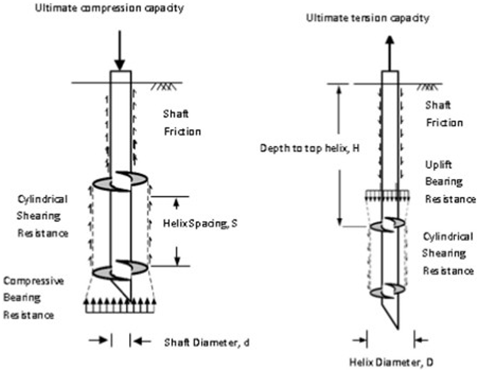
Figure2 Forces involved in cylindrical shear model under compression and tension(Nasr,2004)
It is supposed through the cylindrical shear method that a cylindrical shear failure surface is formed which connects the top and bottom helices, shown in above figureas having an axial capacity equal to the sum of the end bearing resistance below the bottom helix for compression and above it for tension, the sum of shear resistance along the cylindrical shear surface and the shaft friction above the top helix (e.g.Zhang et al., 1998; Livneh and Naggar, 2008; Tappenden et al., 2009; Sakr, 2009,2011;Hawkinsand Thorsten,2009).Equations related to the cylindrical shear method were consequent of the number of helices, the pile geometry, the soil conditions as well as the helical spacing(Nasr,2009).
The inter-helix spacing of bearing plates on the pile and the embedment ratio areseenaskeyparametersintheanalysisanddesignofthecompressivebearing capacity of screw piles in cohesion less soils. Zhang (1999) has recommended that screw piles under compressive or tensile loads with an embedment ratio greater than5 be classified as deep foundations, whereas those with an embedment ratio less than 5be classified ass hallow foundations.
Multi-helix screw piles under deep conditions:
|
D=Diameterofhelix |
ϒ=SoilDensity |
|
Ht=Depthoftophelix |
Hb=Depthofbottom helix |
|
Heff = Effective length of pile above top helix i.e.(Ht– D) |
Ku=Lateralearthpressurecoefficientinuplift |
|
AH=Areaofbottomhelix |
Ps=Perimeterofscrew shaft |
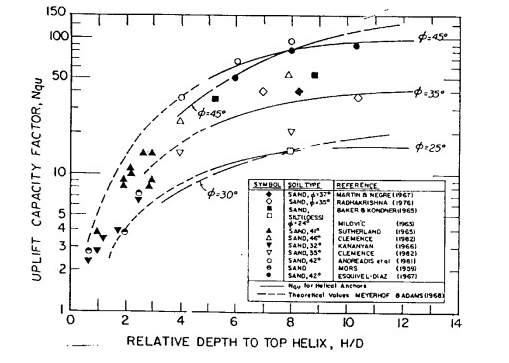
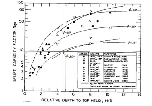
Figure3 Breakout Factor with Embedment DepthRatio(Mitschand Clemence,1985)
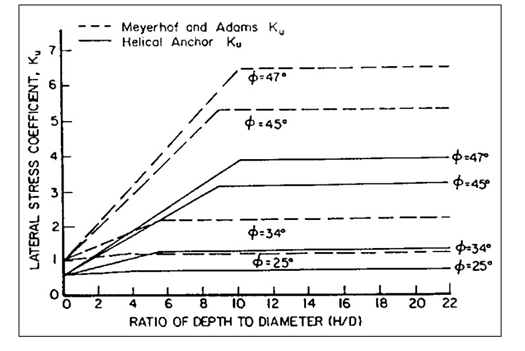
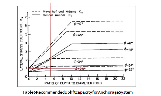
Figure 4 Recommended Lateral Stress Values (Ku) for Helical Anchors (Mitsch andClemence,1985)
Calculation of Lateral Capacity
As a result of wind earthquake, waves, impact and lateral earth pressure most structures are subjected to lateral loads and moments in addition to the axial downward loads due to gravity. If these structures are supported on deep foundations, the foundations have to be designed for lateral loads so that they are safe against geo technical failure, structural failure,and excessive deflections.
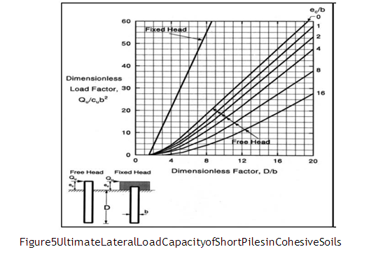
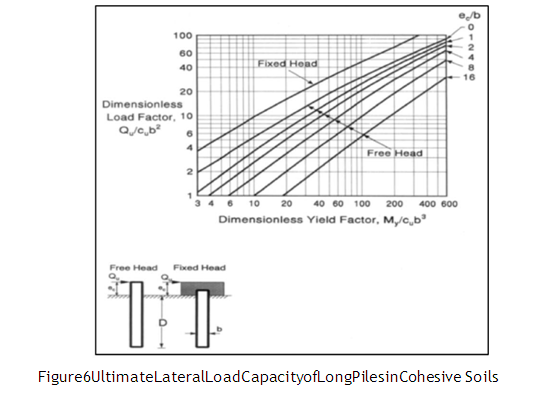
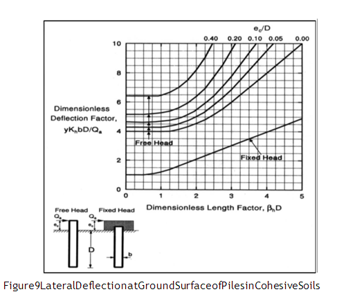
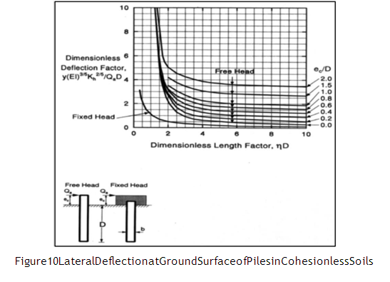
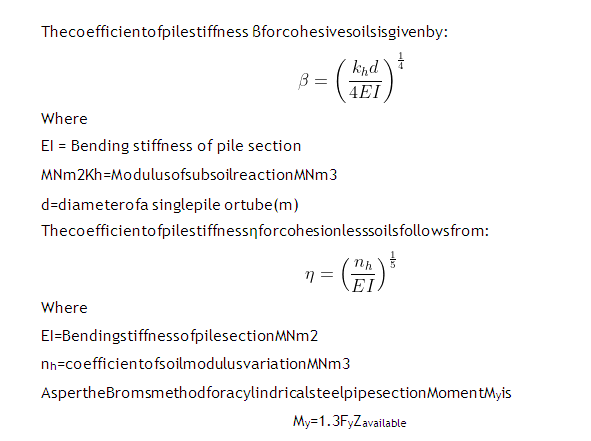
In engineering practice to withstand lateral load, laterally loaded piles are most commonly in use and in order to analyze them a number of theoretical methods are available such as the sub grade reaction approach by Barber (1953) and Matlock and Reese (1960), the ultimate lateral load approach by Broms (1964a). Among these aforementioned methods, Broms’ method is the simplest method to determine the lateral load and pile deflection at the ground surface using a convenient set of curves,ignoring axial load in the pile.
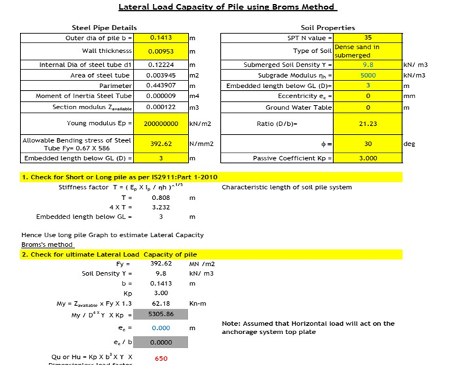
The lateral load-carrying capacity of a pile depends on the properties of the soil in which it is embedded. Now for this anchorage system horizontal load will be coming from the movement of solar panel. This horizontal load transfer to steel tube to helix part of the anchorage system & simultaneously to the surrounding soil. As horizontal load acting on the steel tube, there are two method to estimate the Lateral capacity of the system
- Horizontal Load Resisted by the Soil around the steel tube
- Horizontal Load Resisted by the steel tube
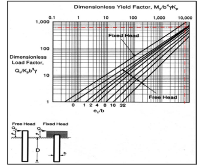
Broms’ method was presented in 964a, 1964b, 1965) for calculating lateral resistance of piles. A pile can be designed to sustain a lateral load based on Broms’ theory of earth pressure by referring to charts and graphs. According to the theory, piles can be divided into two groups; short rigid and long flexible. “Short” pile is one that is rigid enough to move in the direction the load is tending by rotation or translation whereas “long” pier is one that the top will rotate or translate without moving the bottom of the foundation, i.e. a plastic hinge will form. In other word, a pile is considered long when the relative stiffness of the pile with respect to the soil stiffness exceeds certain limits.
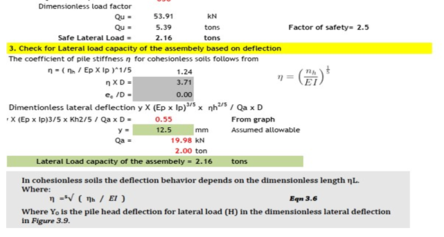
Broms’ developed lateral capacity methods for both short and long piles in cohesive and non-cohesive soil. Broms’ the orized that a short free headed pier rotates about a centre, above the lower end of the foundation, without substantial deformation along its axis. The resistance is the sum of the net of the earth pressures above and the passive earth pressure below the centre of rotation. The end bearing influence or effect is neglected. Like wise, the passive earth pressure on the uppermost1.5 diameters of shaft and the active earth pressure on the back of the pile are neglected. The basic parameters for soil layer system, i.e. depth of each layer, type of soil, fineness of cohesionless soil, Field SPT value (N), location of GWT from GL,head condition of pile, pile material, unit weight of soil (γ), embedded pile length(D),design parameter(deflection/load),working load or allowabled eflection,eccentricity (ec) etc. and basic parameters for pile i.e. diameter of pile (b), bar dia,bar no., clear cover, yield stress of steel (fy), compressive strength of concrete (f’c)etc.
Design Parameters
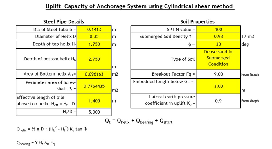
Following design parameters was used to estimate the Lateral & Uplif the lical pile capacity
- 5mm anticipated deflection was considered to estimate lateral pile capacity.
- From the field data N value is more than 100 & hence for design purposeΦ=30 degconsidered
- 980 to 2.040gm /cc &hence for design purpose 1.980gm/cc considered.
- Sub merged density of the soil=0.980gm/cc
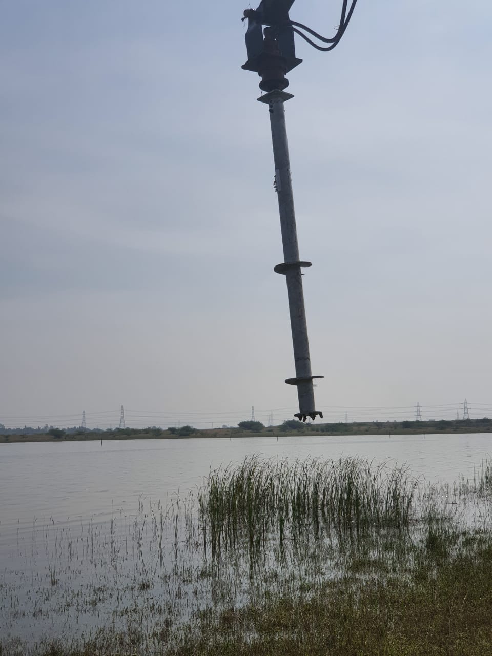
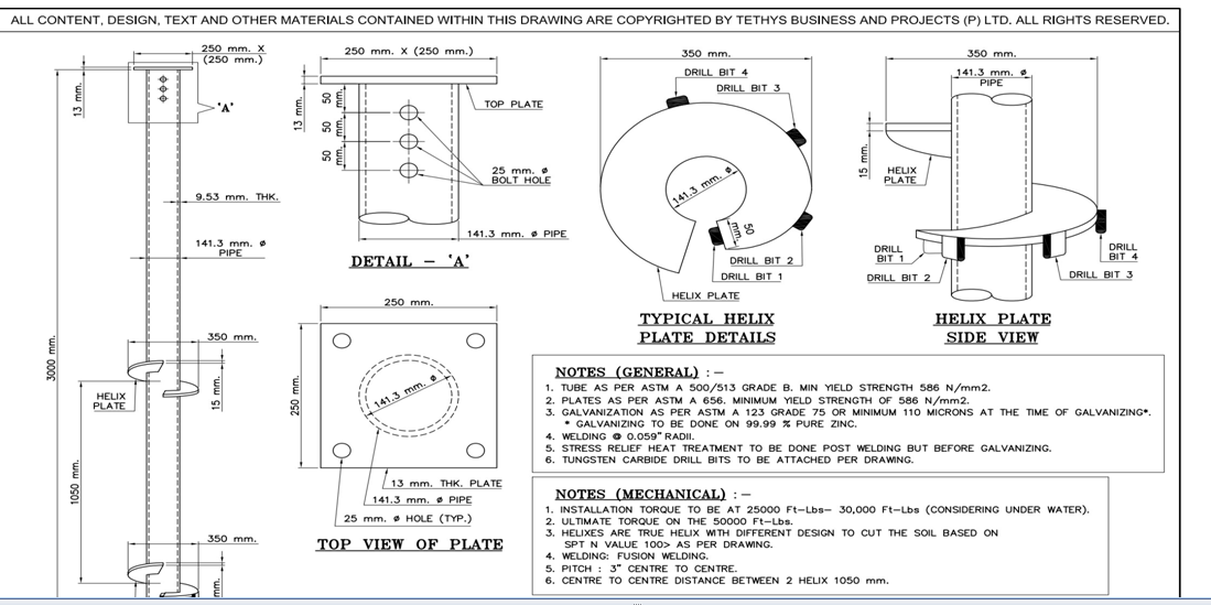
- Diameter of the anchorage shaft/tube=141.3mm
- Length of the anchorage system=3.00m
- Helixdia=0.35m
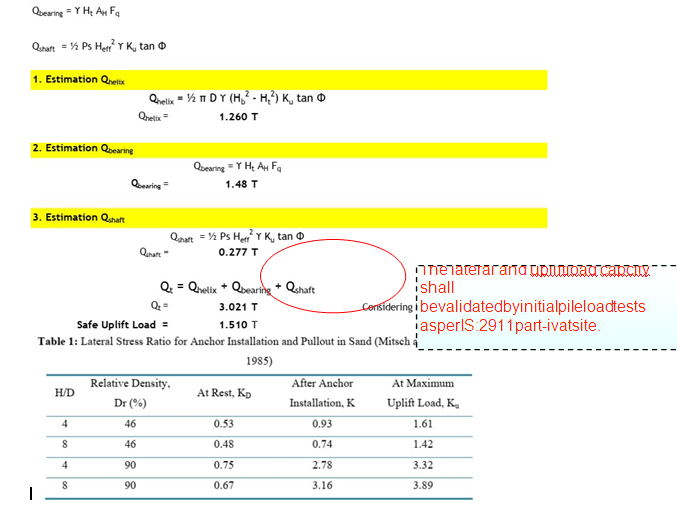
Geotechnical Calculations Uplift Capacity as per Cylindrical shear method
Refer Section 3.1. following are the design parameter to estimate uplift load carrying capacity of the anchorage system;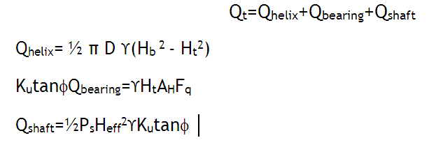
|
ShaftDiain mm |
Dia ofAnchorage System |
Founding Depth ofbelowbedlevelin m |
DesignMethodology |
UpliftCapacity(T) |
|
141.3 |
350mm |
3.00 |
Cylindrical ShearMethod |
1.510 |
Lateral Capacity for Anchorage System(Broom Method)
One of the most common and simplified method is proposed by Broms (1965) that determines the lateral load capacity and pile deflection at ground surface. Broms usess ever algraphical charts to obtain ultimate bearing capacity and lateral deflection. A pile can be designed to sustain a lateral load based on Broms’ theory of earth pressure by referring to charts and graphs.According to the theory, piles can be divided into two groups;short rigid and long flexible.
Following are the assumption to estimate lateral load carrying capacity of the anchorage assembly.
- SPT assume din the capacity estimation is 100
- Angle of Internal friction for soilf=30(where assumed SPT more than 100 blows)
- Anticipated deflection=12.5mm
- Allowable bending stress of steel Fy=0.67X586=392.62N/mm2
- Sub merged Soil Density=9.80kN/m3
Lateral Capacity for Anchorage System
AsperICC-IBC-2009clause1810-3.3.2Allowable lateral load. Where required by the design, the lateral load capacity of a single deep foundation element or a group there of shall be determined by an approved method of analysis or by lateral load tests to at least twice the proposed design working load. The resulting allowable load shall not be more than one-half of the load that produces a gross lateral movement of 1 inch (25 mm) at the lower of the top of foundation element and the ground surface, unless it can be shown that the predicted lateral movement shall cause neither harmful distortion of, nor instability in, the structure, nor cause any element to be loaded beyond its capacity.”
Considering 12.5 mm lateral deflection which is less than 25 mm as proposed byICC-IBC-2009
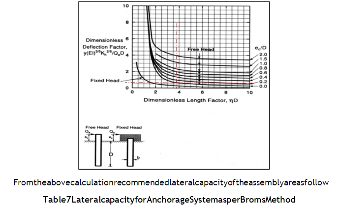
|
ShaftDiainmm |
Diaof AnchorageSystem |
Founding Depth of belowbedlevelinm |
DesignMethodology |
LateralCapacity(T) |
|
141.3 |
350mm |
3.00 |
BromsMethod |
2.00 |
Conclusion & Recommendation for Anchorage System
From the above calculations & results; following are the recommendation for Uplift Capacity & Lateral Capacity, based on the 350 mm anchorage diameter & 3 m length ass how nin the Typical details of anchorage system for Floating Solar Panels
Table 8 Recommended Geotechnical capacity for Anchorage System
|
ShaftDiain mm |
TypeofCapacity |
FoundingDepthbed level inm |
FoundationStrata |
GeotechnicalCapacity(T) |
|
141.3 |
UpliftCapacity |
3.00 |
CompletelyWeatheredRock |
1.510 |
|
LateralCapacityby BromsMethod |
3.00 |
CompletelyWeatheredRock |
2.00 |
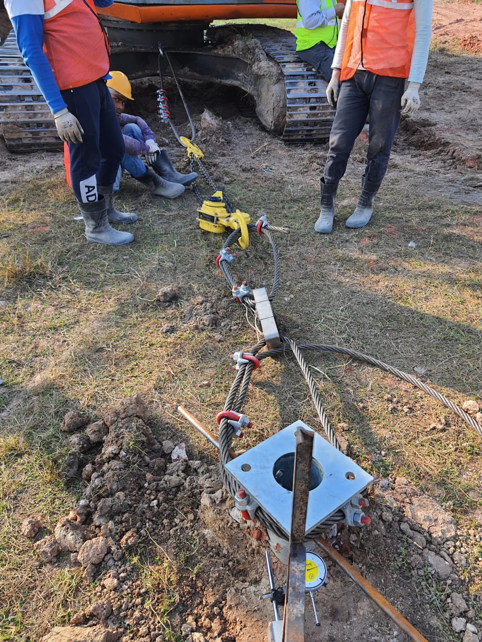
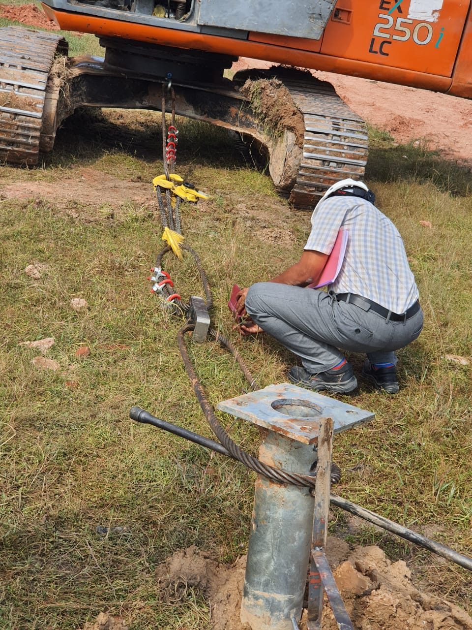
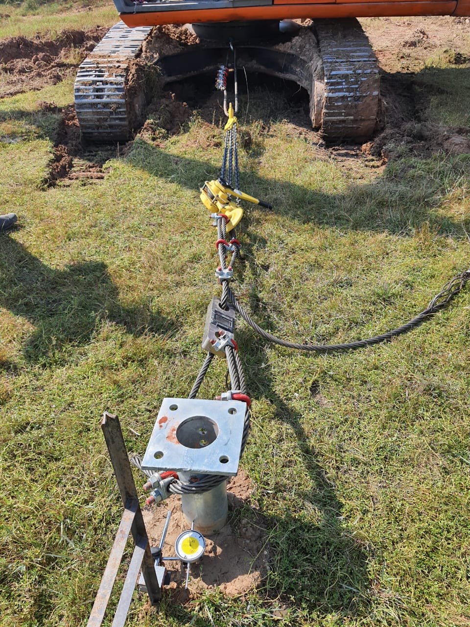
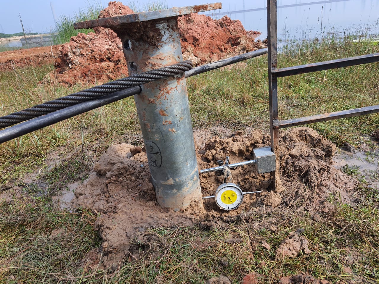
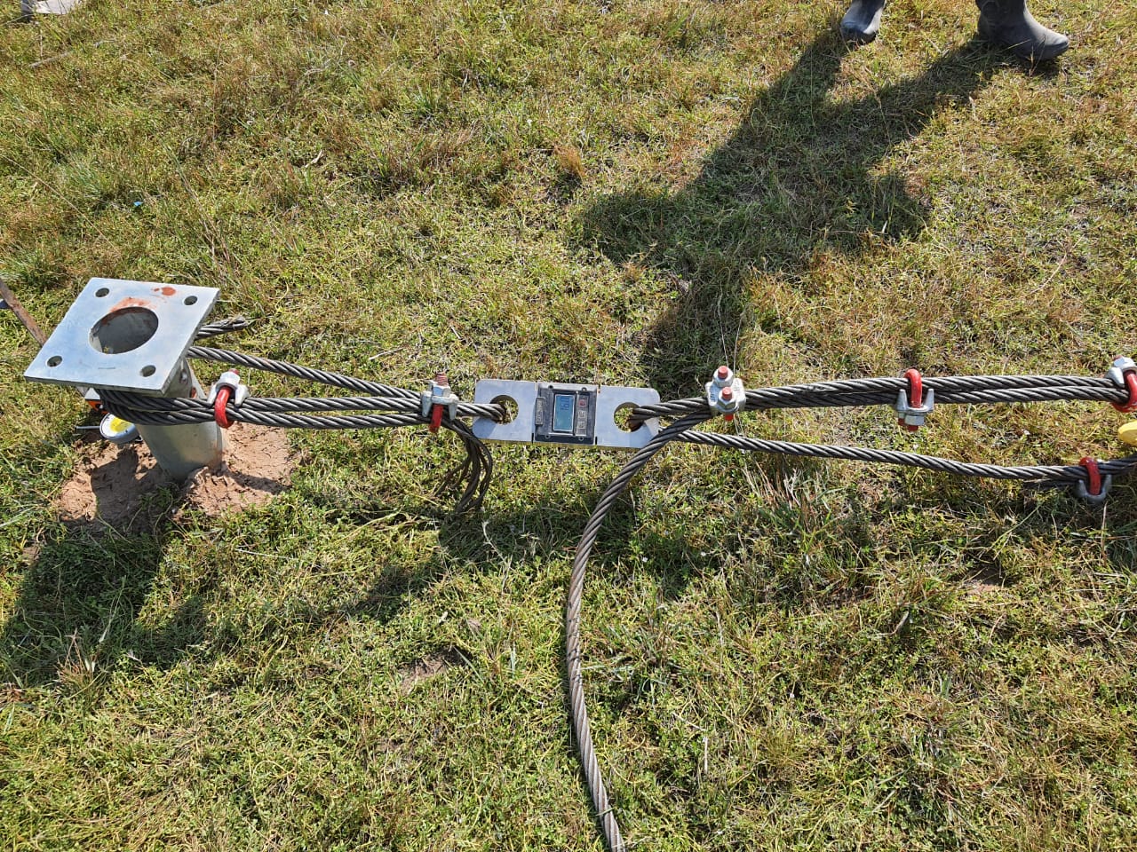
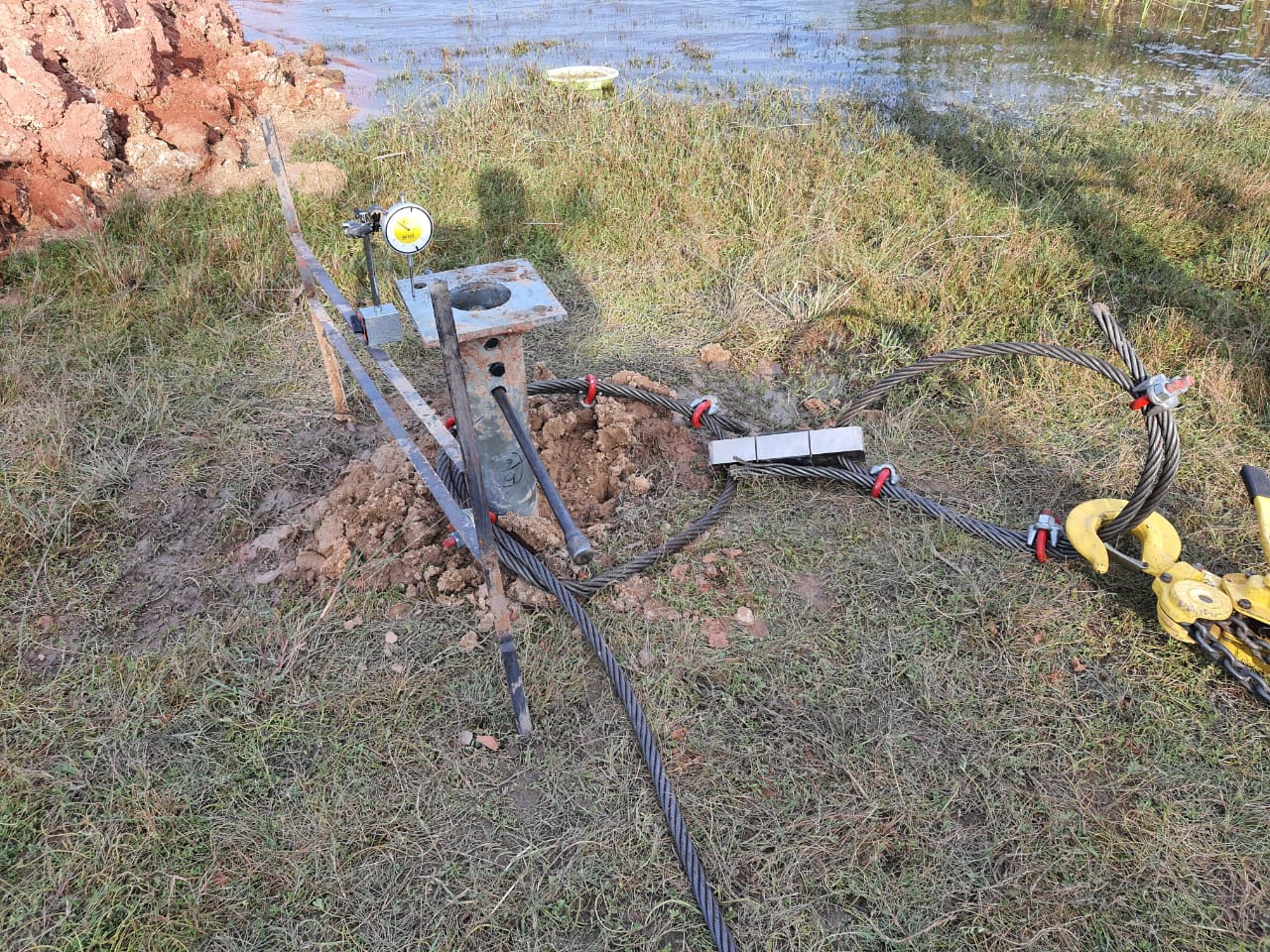
It is a general observation that in actual pull out & lateral load test will be on higher site.
Note: The only method of accurately predicting the load capacity of an anchoragesystem at a specific site is by an onsite proof test (Lateral & Uplift) of the anchor under local conditions, installed and loaded in the same manner as the intended application before adopting above design capacity.
Annexure-I(Report Limitations)
This report has been prepared for M/s Tethys Business and Projects (P) Ltd. This geotechnical assessment report is based on the data provided and from judgement ofundersigned based on his experience. Scope of this assessment report is limited to defining Geotechnical Lateral &Uplift capacity of the anchorage system.
Professional judgments and recommendations are presented in this assessment report. They are based partly on evaluation of the technical information gathered,partly on historical reports and partly on our general experience with sub-surface condition in the area. We do not guarantee the performance of the project in any respect other than that our engineering work and the judgments rendered meet the standards and care of our profession. It should be noted that the estimation of geotechnical Lateral & uplift capacity is based on the various discussion held with theofficer & agreed methodology. Undersigned is not responsible for the construction methodology, quality control at site & the structural stability of the anchorage system. If during construction design loads and/or configuration change,we should be notified immediately in order that we may evaluate effects, if any, on anchorage system performance.The geo technical assessment presented in this report are applicable only to this specific site. This data should not be used for other purposes.
Due to the Limited scope of the Geotechnical consultant (means only estimation of Lateral & Uplift capacity of the anchorage system) & Limited technical in formation about the project shared with the Geotechnical Consultant, before adopting the design parameters for design Purpose Please note that the following points
- Anchorage system(Steel tube&helix) structural design was not in the scope of Geotechnical Consultant. Geotechnical Engineer is not responsible for the quality control at site, installation of anchorage system & behaviour of the anchorage system during design life.
- Due to the array of unknowns both below and above the surface of any anchoring application – the soil medium, installation method, local climate,connections to the anchored structure– no one can guarantee a specific holding strength.Load capacity is not a simple function of“soil class”but also of real time moisture content,compaction,root penetration,installation method,pull-out load angle,and other factors unique to the installation’s time and place.